HOW IT WORKS?

The Ducted Vortex Heating and Cooling System is designed to be straightforward with very few moving parts. Our next step is to produce a commercially viable working prototype for a US tour. Constant development with this technology will be explored throughout its various phases of progress. A light economical affordable system is the ultimate goal. High impact opportunities can be developed from an untapped market once this system proves the science behind it.
This innovation will display how air will flow through the system while creating a vortex that is separated into hot and cold air molecules.
In the Ducted Vortex Heating and Cooling System, as the air enters the advanced rotating spin chamber, it approaches carefully positioned vortex baffle tubes. These tubes take moving airflow and force it into a perfect rotating vortex. Next, it starts spinning the vortex into a counter-clockwise direction. Since there is a wall to the left of the chamber, and the baffle tubes are pointed to the front of the unit, the vortex is forced to the right around the horizontal tube toward the front of the unit. (Not touching the horizontal tube)
As the vortex spins, it forces all the air molecules (hot and cold) around the inner perimeter wall of the main airflow separation tube through centrifugal force. As soon as a large amount of airflow is flowing through the tube and there is an opening in the center of the spin chamber that extends past of opening of the main airflow separation tube. This extension keeps input airflow from accidently entering the tube.
As the airflow spins toward the front of the innovation, the molecules in the hot air are moving at a much faster rate than the molecules of the cold air. Because of this, the molecules in the hot air tend to be further apart from each other, giving the hotter air a lower density. (So it weighs less than the cold air) That means, for the same air volume, cold air has more molecules, and it becomes denser.
The V-Cone assembly is no magic phenomenon that separates the hot for cold air; it is straightforward. As the V-Cone assembly is slightly closed, it limits the space where the air molecules can fit through the front opening to exit. As the air rotates forward, it creates an enormous amount of friction. This friction heats up to over 100 degrees F.
For this reason, since the molecules in the hot air are less dense than the cold air, space only allows the hot air molecules to pass through the opening before any cold air molecules can pass through. The faster it is spinning, the less cold air molecules can enter because the less dense hot air molecules are pushed through first. This action allows it to get more desirable when the vortex is spinning faster and when the position of the V-cone is more closed. Since the vortex never stops, it allows mostly less dense (lighter or hot air) to pass through first.
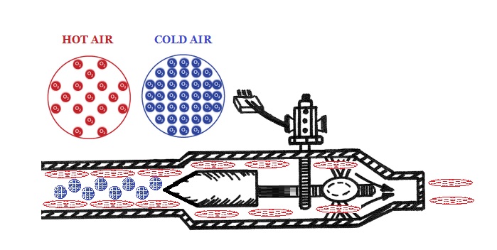
So, what happens to the more dense cold air molecules? Since there is no room for the more dense cold air molecules to exit the front of the V-Cone assembly, as it is positioned closed, there is only one place they can go – The Path of Least Resistance. The cold air molecules automatically keep spinning in the same direction and are forced onto the angle of the V-Cone assembly. Since the cold air molecules are denser than the hot air molecules, they turn around the cone and follow the path of least resistance through the center of the separation chamber, which happens to be the center of the outer perimeter vortex. We have a cold vortex spinning inside a hot vortex. (Just like a natural tornado)
Since the main vortex is spinning around the perimeter of the main airflow separation tube, there is a clear path for the cold air vortex to travel right down the center of the main vortex.
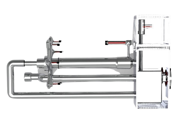
This is where it gets interesting. As the rotating spin chamber is spinning a cold vortex down the center of a hot vortex going in opposite directions, the inventor carefully positioned the ducted fans and air inlet tubes into a centrifugal position that can rotate freely. When the ducted fans are turned on, they turn the entire “rotating spin chamber” in the opposite direction of the vortex spinning on the inside. We have three vortexes running simultaneously with the same input power. As the rotating spin chamber rotates, it captures otherwise wasted mechanical energy and converts it into electrical energy. This is the first smart heating and cooling system that generates electricity while it is working. See prototype DV-4 below.

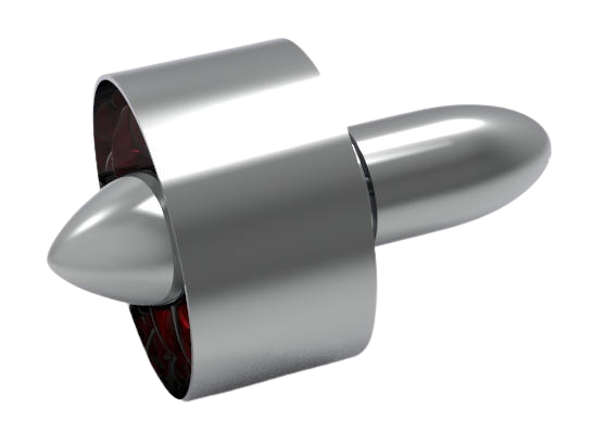
The Ducted Fans
The ducted fan advantageously reduces losses in velocity and pressure from the tips of the propeller blades by varying the cross-section of the duct.
This ducted is equipped a heat sensing clutch plate. The drive portion of a clutch plate typically rotates on a conventional engine with a pully. The other half of the clutch plate rotates with the fan blade, this is called the driven portion. Since there is no pully in this fan clutch, it is constantly engaged until the temperature reaches a certain point. When this happens, the fan clutch disengages and stops the load on the fan blades.
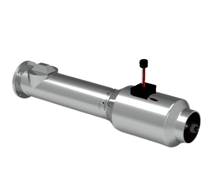
The Delivery Tubes
The ducted fans are connected to the air delivery feed tubes. The delivery tubes can be a variety of sizes depending on the residential or commercial application. Once the air enters the delivery tube, it starts to spiral in a vortex. At the end of the delivery tube is a spring loaded back flow stopper which allows the air movement to only travel in one direction. In the unlikely event that a ducted fan malfunctions, the closed position keeps the airflow from backing up and keeps all remaining ducted fan air flow contained in the spin chamber.
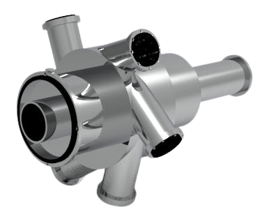
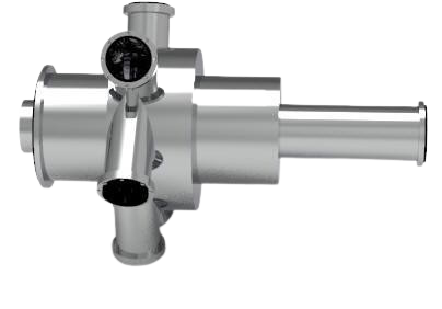
The Advanced Rotating Spin Chamber
The patented rotating spin chamber has any plurality of delivery tubes based on residential or commercial applications. The larger the application, the more delivery tubes are required. In this example, there are 6 delivery tubes and a hot and cold end. The hot end is located to the right and the cold end is located to the left. Once air enters the delivery tubes, it starts a spiral motion which creates an instant vortex around the horizontal tube which is depicted as the tube running from left to right with the dashed line in the center. While the centrifugal force of the vortex in the spin chamber keeps rotating, the angular momentum of the vortex continues to draw air flow at all times.

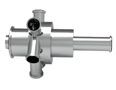
V-Cone Assembly
The V-Cone assembly is controlled by an electric motor that allows it to move forward and backward. As the V-Cone closed toward the main airflow separation tube, it condenses the outer vortex and allows the less dense hot air molecules to pass through the front of the unit.

Main Airflow Separation Tube
Once the vortex air leaves the spin chamber, it enters the main airflow separation tube. Once it hits the Vorxscrew Assembly, the V-Cone, and Gear Mechanism forces the low pressure (cold air) into a reverse direction down the center of the high-pressure vortex. The cold air then enters the center of the horizontal tube leading to the back side of the unit.

Horizontal Tube
The horizontal tube is positioned inside the rotating spin chamber. It allows the more dense cold air molecules to travel toward the back of the unit while the hot travels forward.
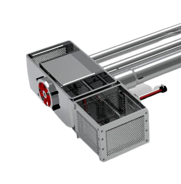
Heat Pump Exchanger
When the heat pump exchanger is in the closed position, hot air is diverted to the back of the unit. This allows the cold air to exit the front. The heat pump exchanger has a metal chassis that houses the 180-degree return fitting. This fitting allows the airflow to reverse in the opposite direction when used in combination with the drive motor that opens and closed the fitting. The heat pump exchanger also contains a plurality of vent openings. These openings house filters that eliminate air born contaminants throughout the entire system. This filtered ambient airflow when mixed with surrounding air creates a perfect temperature which is controlled by thermostat and pressurizes the entire system.
This works in combination with any typical wall mounted thermostat and controls the temperature of the airflow that is distributed throughout the building.

The Reverse Tubes
The reverse tubes move hot and cold air from the heat pump exchanger to and from the front and back of the unit. These tubes have a unique configuration that reverses airflow direction with a flip of a switch.
The Main Unit
The main unit is the backbone of the innovation which comprises all the parts that make it up. Once the main unit is created, it is scalable to fit a variety of residential and commercial applications which include window and air conditioning units for home, business, and apartment complexes. Complete replacement or new units for residential homes, and larger units for commercial buildings and warehouses.

Self-Cooling Electronics
The Ducted Vortex Heating and cooling system always has hot and cold air running simultaneously. It is our intent to use a small permanent shaft chamber that is routed from the cold outlet directly to the electronics. This will blow cold air over the electronics the entire time the unit is on. It makes no difference if the end user is using hot or cold to cool their home, it will always blow cold air on the electronics.

Visually Appealing
Every model we build will be visually appealing and futuristic.
This Prototype (DV-4) is mostly 3-D Printed from CAD files. The inventor used a custom molding system that makes the outside frame feel and look like industrial plastic. The market-ready prototype will be made out of lightweight industrial-strength aluminum.
This video demonstrates the basic functions.
What is a Ducted Fan?
Sound inside home
Heat Pump Exchanger